-40%
Complete Scientific Atlanta 1780 Phase Amplitude Programmable Microwave Receiver
$ 1055.47
- Description
- Size Guide
Description
THE SERIES 1780 PROGRAMMABLE MICROWAVE RECEIVERCOMPLETE OPERATIONAL SYSTEM IN EXCELLENT CONDITION WITH MANY OPTIONS
ATTENTION:
This is the first time such a system has been made available on eBay and will most probably be the last time anyone will be able to get one anywhere. This is a complete system we are decommissioning. It is fully functional and demonstrable (see photographs).
The Series 1780 Programmable Phase/Amplitude Receiver
is a versatile microprocessor-based data acquisition receiver offering many new features and capabilities including IEEE-488 standard bus compatibility, high data rate capability, programmable IF system bandwidth, programmable data averaging, programmable IF system calibration, improved amplitude and phase stability, and an 80 dB continuous dynamic range with a .01 dB resolution.
These features allow the receiver to be programmed to provide optimum performance for a wide variety of manual and automatic antenna range measurement situations.
RECEIVER CHARACTERISTICS
A receiver designed to perform as a general purpose phase/amplitude measurement receiver having features required for general antenna pattern range data measurement should have the following:
• wide frequency range
• good sensitivity
• adequate dynamic range
• capability of mixer remoting and separation
• two-channel or three-channel capability
• automatic control capability
• high data-rate capability
• frequency agility
• digital/analog data output capability
• accurate phase/amplitude data readout
• good long term stability
• high interchannel isolation
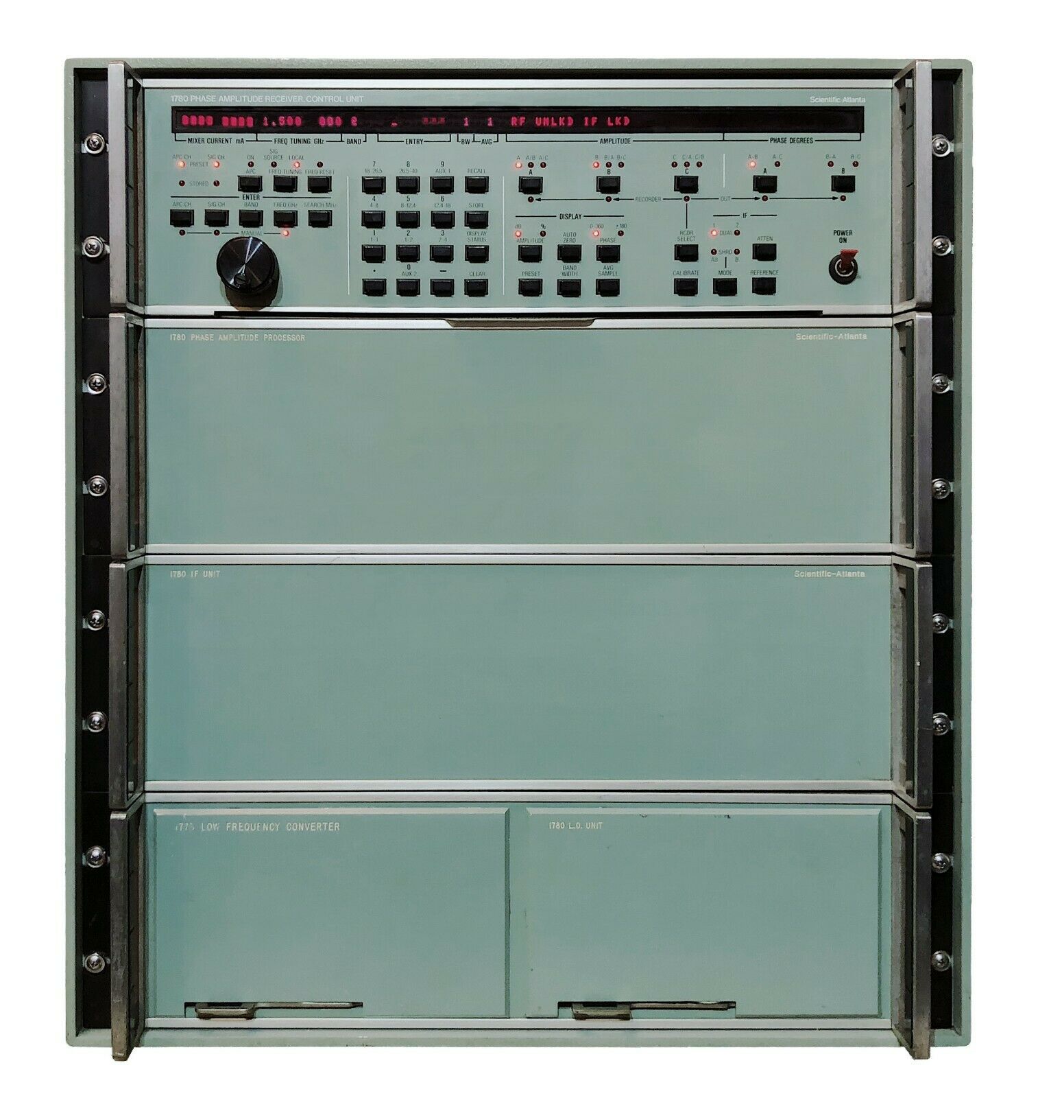
The 1780 system assembly consists of four rack mounting subunits, each of which is 51/4 inches high. All receiver controls and displays are mounted on the front panel of top unit, which is the microprocessor-based control unit. This panel includes a 72 character alphanumeric display, a keypad, control buttons and LED indicators.
An RF switch operating at a 27.5 kHz rate and synchronized with an IF switch located in the IF unit directs the CH A and CH B RF inputs to the CH A and CH B IF channels respectively. This arrangement provides three input/output channels using two mixers and offers improved phase measurement stability when phase is measured between SIG CH A and SIG CH B. Since the signal-channel mixers and associated receiver-to-mixer cable are common to channels A and B, phase errors due to mechanical or thermal effects in the mixer or cable will cancel.
The microprocessor-based phase/amplitude processor processes the 5020-Hz IF inputs. The processing consists of predetection filtering, post-detection filtering, phase measurements, amplitude function generation (linear, logarithmic or direct ratios), amplitude measurements and output-data formatting. All operations are carried out for three-amplitude channels and two phase channels. The phase/amplitude processor furnishes both a digital (byteserial) output and an analog output for recording. The recorder output can be programmed to record either any single amplitude channel, any single phase channel or to be OFF.
A total of thirty-two front-panel-programmable service-mode routines are provided in the receiver to facilitate alignment and maintenance. The service modes permit the receiver keyboard and display to be used in an alternate mode of operation. In this mode normal receiver operations are suspended and stored procedures may be used to (1) enter auxiliary frequency band information, (2) enter preset mixer currents and receiver options, (3) to exercise tests and programs that confirm system operation, and (4) assist in general troubleshooting.
RECEIVER OPERATING MODES
The Series 1780 receivers have four programmable operating modes (see Figures 4 and 5). The RF/IF signal paths for operating in the DUAL 1 mode are shown by Figure 4A. In this configuration, the SIG CH A RF and the APC CH RF are converted to IF in the appropriate channels.
The RF/IF signal paths when operating in the DUAL 2 mode are shown by Figure 4B. The signal paths are identical to those of the DUAL 1 mode except the RF switch is switched to select the SIG CH B RF input. The DUAL 1/DUAL 2 modes provide the user with a means of using the external RF switch as a programmable coaxial relay.
The SHARED AB mode signal paths are shown by Figure 5B. When operating in this mode, the RF SIG CH A and the RF SIG CH B inputs are synchronously switched at 27.5 kHz such that the signal channel passes both the CH A IF and CH B IF signals simultaneously. This configuration has three RF inputs and three RF outputs.
The DUAL 1 mode (Figure 4A) and the SHARED B mode (Figure 5C) SIG CH RF/IF paths are identical to the two switched RF/IF signal paths of the SHARED AB mode. Static evaluation of either of the two SHARED AB RF/IF signal paths can be accomplished by operating either in the DUAL 1 or the SHARED B mode.
AUTOMATIC CONTROL
All programmable functions of the receiver are controllable through the IEEE-488 standard bus (see Figure 6). During operation the receiver is able to both talk and listen and can be operated with other compatible instruments.
Programmable receiver functions are as follow:
• Automatic/Manual
• IF Mode
• IF Attenuation (CH A, CH B, CH C) Mixer Current (APC CH and SIG CH)
• Frequency
• Search Width
• APC ON/OFF
• Bandwidth (Predetection Filtering)
• Data Averaging (Post-Detection Filtering)
• Display Functions
• Remote or Local Tuning Reference ON/OFF
• Calibrate (IF System) Recorder Output Select Auto Zero
• Preset (Phase and Amplitude)
• Front Panel (Store Recall)
FREQUENCY RANGE
When the Series 1780 receiver is operated with the optional low-frequency converter (.1 to 1.0 GHz) and with optional fixed-tuned mixers, the receiver is programmable from 0.1 GHz to 100 GHz. Selection of operating frequency may be any of the following procedures.
• digital (manual) programming at receiver front panel
• analog (remote) programming from Series 2150 signal source
• digital (automatic) programming through the IEEE-488 standard bus
When the Series 1780 receiver is operated in Scientific-Atlanta automatic systems, frequency programming is accomplished through the system signal source rather than through the IEEE-488 standard bus. When operated in this manner, the receiver remains phase-locked to the signal-source frequency during a frequency stepping interval. This eliminates the need to unlock, step frequency, search and relock the receiver to the signal source to each programmed frequency resulting in the shortest possible frequency step interval.
Frequency programming at frequencies above 18.0 GHz where mixer current readjustment may be necessary when frequency is changed is made possible by the ability of the receiver to store in memory up to ten complete front-panel programs. Each stored front-panel program can be preset for frequency, mixer current, attenuation settings, etc. These stored front-panel programs can be recalled either by manually using the receiver front-panel controls or automatically through the IEEE-488 standard bus.
An additional feature of the receiver is the FREQ. RESET, which automatically updates (corrects for signal source or receiver local oscillator frequency drift) each stored tuning command used to preset the local oscillator frequency prior to initiating phase-lock. This feature improves the frequency preset accuracy, reducing the search frequency range requirements necessary to provide phase lock. The local oscillator search range is programmable to be either zero or any 1 MHz increment between ±10 MHz to ±400 MHz. Since the product of peak-to-peak search width and search rate is a constant (approximately 2000 MHz/second), the narrower searchwidths are, associated with the higher scan rates. For a search width of ±10 Hz the scan rate is 100 Hz and the average time to search and phase lock is 5 milliseconds (the worse-case time is 10 milliseconds).
REMOTE OPERATION DATA RATE
When the receiver is operated under remote control, the following two conditions occur:
• Receiver front panel controls are disabled.
• "REMOTE D" or "REMOTE F" is displayed on the receiver front panel.
"REMOTE D" indicates that data will be displayed on the receiver front panel while in REMOTE.
"REMOTE F" indicates that data will not be displayed on the receiver front panel while in REMOTE.
The "REMOTE F" mode is the fast mode, since data conversions for the front panel are not being performed. When operating in the "REMOTE F" mode, the receiver is capable of acquiring, sampling, processing and outputting multiple channel phase/amplitude data at rates of 100 or more data samples per second. The actual data rate is dependent on the REMOTE operating mode selected, the number of data channels being processed, the BANDWIDTH selected and the AVERAGED SAMPLES selected.
BANDWIDTH AND AVERAGE SAMPLES
The Series 1780 Programmable Microwave Receiver offers a choice of nine bandwidths (7 Hz to 1600 Hz) and twelve selections of averaging of data samples (1 to 2048 samples averaged). When the system bandwidth is decreased, the sensitivity increases and response speed decreases. If bandwidth is increased, sensitivity decreases and response speed increases. When the number of data samples averaged is increased, the sensitivity is not affected; however, variance of the noise is decreased and the system response speed is decreased. If the number of data samples is decreased, less noise averaging occurs and the system response is increased.
The choice of operating bandwidth and average samples is determined by the system requirements for sensitivity and data rate. If maximum data rate is required, the widest BANDWIDTH (1) and the minimum AVERAGE SAMPLES should be selected. If, on the other hand, sensitivity and dynamic range are of primary importance, then the narrower bandwidths and greater number of AVERAGE SAMPLES should be selected. Table 2 shows the relationship between the BANDWIDTH code and the 3 dB predetection IF bandwidth.
IF SYSTEM The IF
modules of the Series 1780 receiver have been designed using integrated circuit amplifiers as the basic amplifier gain stages. All main IF amplifiers are powered from power sources that are double-regulated. These design factors have resulted in an IF system with excellent gain and phase stability versus temperature and power line voltage change and phase-tracking between channels.
The phase and amplitude stability of the IF system is further improved by a programmable calibration procedure. A stable, coherent 45.000 MHz signal is supplied to the inputs of the SIG CH and APC CH IF preamplifiers as a calibration reference. An automatic calibration routine calibrates phase and amplitude of each IF channel in onedB amplitude steps over a 40-dB dynamic range. Error correction is performed digitally. The entire calibration procedure for three amplitude channels and two phase channels is accomplished in approximately ten seconds.
Each IF channel and corresponding amplitude data output has a continuous operating dynamic range of 80 dB with an 0.01 dB resolution over the full 80 dB dynamic range. The resolution of the phase data readout is 0.1 degree.
The attenuation of each IF channel is programmable in 1.0 dB steps over a 40 dB dynamic range. Programmable phase presets and amplitude presets permit amplitude and phase channel output data to be preset to desired reference levels. An AUTO ZERO procedure automatically adjusts the output reading of any phase or amplitude channel to full scale (00.00 dB log amplitude or 000.0 degrees phase).
This auction consists of one 1780 Programmable Microwave Receiver as shown including:
-
1x
1780 PHASE AMPLITUDE RECEIVER CONTROL UNIT with rack rails (as shown in rack system photos)
- 1x 1780 PHASE AMPLITUDE PROCESSOR
with rack rails
(as shown in rack system photos)
- 1x 1780 IF UNIT
with rack rails
(as shown in rack system photos)
- 1x 1780 HALF-RACK rackmount subassembly
with rack rails
(as shown in rack system photos)
- 1x 1773 LOW FREQUENCY CONVERTER
- HALF-RACK
(as shown in rack system photos)
- 1x 1780 L.O. UNIT
- HALF-RACK
(as shown in rack system photos)
- 1x 12U Scientific Atlanta system rack
(as shown in rack system photos)
- 1x Set all Cable assemblies with Labels
(as shown in rack system photos)
Additionally included in this auction:
- 1x spare
-
1x spare
1780 PHASE AMPLITUDE PROCESSOR
- 1x spare
1780 IF UNIT
-
1x spare
1780 L.O. UNIT
- 1x 1780 SERIES STORAGE DRAWER - HALF-RACK
- 3x Scientific Atlanta model 14-5 harmonic mixer
- 1x
NARDA model 3044-10 Coaxial Directional Coupler
- 1x
NARDA model 3044-30 Coaxial Directional Coupler
- 1x
Series 1780 Programmable Microwave Receiver
Operators Manual
- 1x Series 1780 Programmable Microwave Receiver Maintenance Manual
- 1x
Technical Calibration Procedure for
Series 1780
Programmable Microwave Receiver
- 1x
Schematics for
Series 1780
Programmable Microwave Receiver
SEE OUR EXCELLENT EBay FEEDBACK & BUY WITH CONFIDENCE
* * * LET US KNOW IF YOU NEED MORE INFORMATION OR PHOTOGRAPHS * * *
* * * WE SHIP WORLDWIDE
(EXPORT RESTRICTIONS MAY APPLY) * * *
* * * SAFE & RELIABLE FREIGHT PACKING & SHIPPING* * *
!!! GOOD LUCK BIDDING !!!
* * * CALL:
+1.303.931.8823
WITH ANY QUESTIONS * * *
SEE OUR EXCELLENT EBay FEEDBACK & BUY WITH CONFIDENCE
This System Can Be PICKED-UP LOCALLY FREE OF CHARGE, Or SHIPPED ANYWHERE IN THE WORLD.
Buyers Who Have Paid For System Are Invited To Inspect The System Prior To Pickup/Shipping
And Are Eligible For A Full Refund If Inspection Does Not Meet Their Full Satisfaction.
* ABSOLUTELY NO RETURNS OR REFUNDS WILL BE ACCEPTED AFTER THE SYSTEM LEAVES OUR PREMISES.
* No N.A.D's. ("Not As Described") - Come And See The Quality For Yourself
* No RETURNS - No EXCEPTIONS.
SEE OUR EXCELLENT EBay FEEDBACK & BUY WITH CONFIDENCE
Our Store Has A Perfect Record Of Trust Selling The Highest Quality High-End Communication Equipment Since 1990
Preferred Payment Method Is Via Direct Transfer – If PayPal Or CC Is Used, Buyer Pays 3.5% PayPal/CC Fee
SEE OUR EXCELLENT EBay FEEDBACK & BUY WITH CONFIDENCE
!!! GOOD LUCK BIDDING !!!
* * * CALL:
+1.303.931.8823
WITH ANY QUESTIONS * * *
SEE OUR EXCELLENT EBay FEEDBACK & BUY WITH CONFIDENCE
